Opis
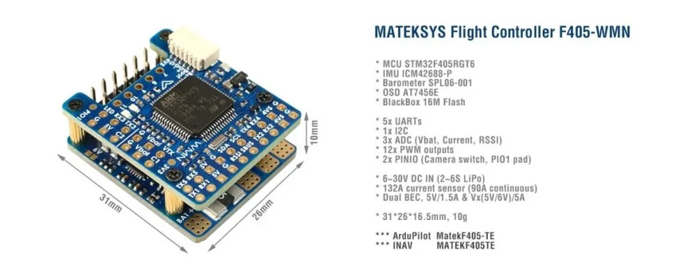
FC Specifications
- MCU: STM32F405RGT6, 168MHz , 1MB Flash
- IMU: ICM42688-P
- Baro: SPL06-001
- OSD: AT7456E
- Blackbox: 16M Flash
- 5x UARTs, 1x Softserial_Tx option(INAV)
- 12x PWM outputs
- 1x I2C
- 3x ADC (VBAT, Current, RSSI)
- 1x spare PINIO
- USB/Beep Extender with Type-C(USB2.0)
- Built in inverter on UART2-RX for SBUS input
- Switchable Dual Camera Inputs
Power
- 6~30V DC IN (2~6S LiPo)
- 132A Current Sense (INAV Scale 250, ArduPilot 40A/V)
- PDB/Current sense resistor: 90A continuous, 132A burst.
- BEC 5V 1.5A for FC & Peripherals
- BEC Vx 5A for servos, 5V/ 6V option
- Vbat for VTX and camera
- LDO 3.3V 200mA
- Battery Voltage Sensor: 1k:20k
FC Firmware
- ArduPilot: MatekF405-TE
- INAV: MATEKF405TE (INAV 5.0 or newer)
Physical
- Dimensions: 31 x 26 x 16.5 mm
- Mounting: 22 x 22mm, Φ2mm
- Weight: 10g
Including
- 1x F405-WMN
- 1x USB(Type-C)/Beep (Passive buzzer) Extender + 20cm JST-SH-6P to JST-SH-6P cable for USB extender.
- Dupont 2.54 pins (Board is shipped unsoldered)
INAV Mapping
INAV MultiRotorINAV Plane
PWMS15 V tolerant I/OTIM8_CH4MotorMotor
S25 V tolerant I/OTIM8_CH3MotorMotor
S35 V tolerant I/OTIM1_CH3NMotorServo
S45 V tolerant I/OTIM1_CH1MotorServo
S55 V tolerant I/OTIM2_CH4MotorServo
S65 V tolerant I/OTIM2_CH3MotorServo
S75 V tolerant I/OTIM2_CH2MotorServo
S85 V tolerant I/OTIM2_CH1MotorServo
S95 V tolerant I/OTIM12_CH1ServoServo
S105 V tolerant I/OTIM13_CH1ServoServo
S115 V tolerant I/OTIM4_CH1ServoServo
LED5 V tolerant I/OTIM3_CH42812LED2812LED
ADCVbat Pad1K:20K divider builtin
0~30VVbat ADC
ADC_CHANNEL_1INAV voltage scale 2100
Curr pad0~3.3VCurrent ADC
ADC_CHANNEL_2scale 150
RSSI Pad0~3.3VRSSI ADC
ADC_CHANNEL_3Analog RSSI
No Pad AirS ADC
ADC_CHANNEL_4
I2CI2C15V tolerant I/OCompassQMC5883 / HMC5883 /MAG3110 / LIS3MDL
OLED0.96″
onboard BarometerSPL06-001
Digital Airspeed sensorMS4525
Temperature sensor
UART
5V tolerant I/OUSB USB
TX1 RX15V tolerant I/OUART1USER
TX3 RX3UART3USER
TX4 RX4UART4USER
TX5 RX5UART5USER
No PadUART6–
TX2 RX2
SBUS5V tolerant I/OUART2RC input/Receiver
Sbus padfor SBUS receiver, Sbus pad = RX2+inverter
RX2 padIBUS/DSM/PPM
TX2 & RX2CRSF
TX2 padSmartPort Telemetryenable Softserial_Tx1
TX2 padFPORT, uninverted S.Port/F.Port signal (hacked)
TX2 padSRXL2
PINIO
- PINIO1 /PIO1 pad, Low Level by default, Low/High level switchable by Mode-USER1
- PINIO2 is for camera input switch by Modes-USER2
Tips
- F405-WMN has INAV fw preloaded for QC
- Download INAV firmware 4.1.x from our website. Target MATEKF405TE is not listed in INAV configurator 4.x.x,
- You may download INAV fw 5.0 or newer directly from INAV configurator 5.x or newer.
Ardupilot Mapping
ArduPilot
PWM
5V tolerant I/OS1PWM1 GPIO50TIM8_CH4DMA/DShotGroup1
S2PWM2 GPIO51TIM8_CH3DMA/DShot
S3PWM3 GPIO52TIM1_CH3NDMA/DShotGroup2
S4PWM4 GPIO53TIM1_CH1DMA/DShot
S5PWM5 GPIO54TIM2_CH4DMA/DShotGourp3
S6PWM6 GPIO55TIM2_CH3DMA/DShot
S7PWM7 GPIO56TIM2_CH2DMA/DShot
S8PWM8 GPIO57TIM2_CH1DMA/DShot
S9PWM9 GPIO58TIM12_CH1NO DMAGourp4
S10PWM10 GPIO59TIM13_CH1NO DMAGourp5
S11PWM11 GPIO60TIM4_CH1NO DMAGourp6
LED padPWM12 GPIO61TIM3_CH4DMA/DShotGourp7
SERVO12_FUNCTION 120, NTF_LED_TYPES neopixel
Mixing Dshot and normal PWM operation for outputs is restricted into groups, ie. enabling Dshot for an output in a group requires that ALL outputs in that group be configured and used as Dshot, rather than PWM outputs.
If servo and motor are mixed in same group, make sure this group run lowest PWM frequency according to the servo specification. ie. Servo supports Max. 50Hz, ESC must run at 50Hz in this group.
ADCVbat Pad1K:20K divider builtin
0~30VVbat ADC
onboard battery voltage
BATT_VOLT_PIN
BATT_VOLT_MULT14
21.0
Curr pad0~3.3Vcurrent sensor ADC
onboard current sense
BATT_CURR_PIN
BATT_AMP_PERVLT15
40
RSSI Pad0~3.3VRSSI ADC
Analog RSSIRSSI_ANA_PIN
RSSI_TYPE8
2
–––––
I2CI2C15V tolerant I/OCompassCOMPASS_AUTODEC1
onboard Baro SPL06-001Address0x76
Digital Airspeed I2C
MS4525
DLVR-L10DARSPD_BUS
ARSPD_TYPE
ARSPD_TYPE1
1
9
UART
5V tolerant I/OUSBUSB consoleSERIAL0
TX1 RX1USART1with DMAtelem1SERIAL1
TX3 RX3USART3NO DMAtelem2SERIAL2
TX5 RX5UART5NO DMAGPS1 ***SERIAL3
TX4 RX4UART4NO DMAGPS2 ***SERIAL4
––––SERIAL5
TX2 RX2
SBUSUSART2with DMARC input/ReceiverSERIAL6
RX2IBUS/DSM/PPMBRD_ALT_CONFIG 0
Default
Sbus padSBUS
TX2 & RX2CRSFBRD_ALT_CONFIG 1
SERIAL6_PROTOCOL 23SERIAL6_OPTIONS 0
TX2 uninverted FPort (hacked)SERIAL6_OPTIONS 4
TX2SRXL2SERIAL6_OPTIONS 4
- *** If connecting just one GPS to UART4(TX4/RX4), pls set UART5 SERIAL3_PROTOCOL = -1 or non “5”. otherwise ArduPilot will stop searching for GPS during bootup if not found on the first port(SERIAL3, UART5) configured for GPS protocol.
- If sending highspeed serial data (eg. 921600 baud) to the board, use USART1(Serial1) or USART2(Serial6).
Frsky Smartport Telemetry
- non-inverted (hacked) S.Port signal
- any spare Uart_TX
- SERIALx_BAUD 57
- SERIALx_OPTIONS 7
- SERIALx_PROTOCOL 4 or 10(for yaapu)
DJI FPV OSD (ArduPilot 4.1)
- OSD_TYPE = 3
- SERIALx_PROTOCOL = 33
- MSP_OPTIONS = 0 (polling mode)
Relay(PINIO)
- PINIO1, PIO1 pad, Low Level by default
- PINIO2, Camera switch, C1 ON by default
# GPIOs
- PA4 PINIO1 OUTPUT GPIO(81) LOW //PIO1 pad
- PB5 PINIO2 OUTPUT GPIO(82) LOW //camera switch
# RCx_OPTION: RC input option
- 28 Relay On/Off
- 34 Relay2 On/Off
- 35 Relay3 On/Off
- 36 Relay4 On/Off
e.g.
- RELAY_PIN 81 //PIO1 GPIO
- RC7_OPTION 28 //Relay On/Off, Use CH7 of Transmitter to control PIO1 Low/High Level
- RELAY_PIN2 82 //Camera switch GPIO
- RC8_OPTION 34 //Relay2 On/Off, Use CH8 of Transmitter to control high/low level on PB5 pad
The configured feature will be triggered when the auxiliary switch’s pwm value becomes higher than 1800. It will be deactivated when the value falls below 1200.
Check the pwm value sent from the transmitter when the switch is high and low using the Mission Planner’s Initial Setup >> Mandatory Hardware >> Radio Calibration screen. If it does not climb higher than 1800 or lower than 1200, it is best to adjust the servo end points in the transmitter.