Promocja!

MATEK H743-SLIM V3 Flight Controller Bezpieczna płatność

Pierwotna cena wynosiła: 563,00 zł.Aktualna cena wynosi: 225,20 zł.

Bezpieczna i gwarantowana płatność

Akceptowane metody płatności
  • Darmowa i szybka dostawa od 42,99 zł
  • 14 dni na zwrot i zwrot środków
  • Bezpieczne płatności z szyfrowaniem SSL
SKU: SK0038239-PL20260425-102912 Kategoria: Znacznik:

Opis

V3,  IMU ICM42688P, ICM42605
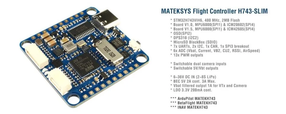
 

FC Specifications

  • MCU: STM32H743VIH6, 480MHz , 1MB RAM, 2MB Flash
  • Board V1.0 IMU: MPU6000 (SPI1) & ICM20602 (SPI4)
  • Board V1.5 IMU: MPU6000 (SPI1) & ICM42605 (SPI4)
  • Board V3 IMU: ICM42688P & ICM42605
  • Baro: Infineon DPS310 (I2C2)
  • OSD: AT7456E (SPI2)
  • Blackbox: MicroSD card socket (SDIO)
  • 7x Uarts (1,2,3,4,6,7,8) with built-in inversion.
  • 13x PWM outputs(including “LED” pad)
  • 2x I2C
  • 1x CAN
  • 6x ADC (VBAT, Current, RSSI, Analog AirSpeed, Vbat2, Cur2)
  • 3x LEDs for FC STATUS (Blue, Red) and 3.3V indicator(Red)
  • 1x SPI3 breakout
  • USB Type-C(USB2.0)
  • 1x JST-SH1.0_8pin connector (Vbat/G/Curr/Rx8/S1/S2/S3/S4)
  • 1x JST-GH1.25_4pin connector (5V/CAN-H/CAN-L/G)
  • Dual Camera Inputs switch
  • 5V/Vbat filtered power ON/OFF switch
  • DJI FPV OSD is supported by any spare UART

Power

  • Vbat Input: 6~36V (2~8S LiPo)
  • BEC: 5V 2A cont. (Max.3A)
  • LDO 3.3V: Max.200mA
  • No Current Sensor built-in
  • ADC Vbat2 pad supports Max. 69V (voltage divider: 1K:20K)
  • Static power: 200mA@5V with Betaflight,  150mA@5V with ArduPilot

FC Firmware

  • ArduPilot(ChiBiOS): MATEKH743
  • BetaFlight: MATEKH743
  • INAV: MATEKH743

Physical

  • Mounting: 30.5 x 30.5mm, Φ4mm with Grommets Φ3mm
  • Dimensions: 36 x 36 x 5 mm
  • Weight: 7g

Including

  • 1x H743-SLIM
  • 6x Silicon grommets M4 to M3
  • 1x JST-SH1.0_8pin cable, 5cm
  • 2x JST-SH1.0_8pin connectors
  • 1x JST-GH-4P to JST-GH-4P cable for CAN port, 20cm


Ardupilot Mapping

PWM
PWM1~PWM13 are Dshot and PWM capable. However, mixing Dshot and normal PWM operation for outputs is restricted into groups, ie. enabling Dshot for an output in a group requires that ALL outputs in that group be configured and used as Dshot, rather than PWM outputs.
If servo and motor are mixed in same group, make sure this group run lowest PWM frequency according to the servo specification. ie. Servo supports Max. 50Hz, ESC must run at 50Hz in this group.S1PB05 V tolerant I/OPWM1 GPIO50TIM8_CH2NGroup1S2PB13.3 V tolerant I/OPWM2 GPIO51TIM8_CH3NS3PA05 V tolerant I/OPWM3 GPIO52TIM5_CH1Group2S4PA15 V tolerant I/OPWM4 GPIO53TIM5_CH2S5PA25 V tolerant I/OPWM5 GPIO54TIM5_CH3S6PA35 V tolerant I/OPWM6 GPIO55TIM5_CH4S7PD125 V tolerant I/OPWM7 GPIO56TIM4_CH1Gourp3S8PD135 V tolerant I/OPWM8 GPIO57TIM4_CH2S9PD145 V tolerant I/OPWM9 GPIO58TIM4_CH3S10PD155 V tolerant I/OPWM10 GPIO59TIM4_CH4S11PE55 V tolerant I/OPWM11 GPIO60TIM15_CH1Group4S12PE65 V tolerant I/OPWM12 GPIO61TIM15_CH2LEDPA85 V tolerant I/O  PWM13 GPIO62TIM1_CH1Group5SERVO13_FUNCTION 120,   NTF_LED_TYPES  neopixel       ADCNo pad
1K:10K divider builtinPC00~36Von board battery voltageBATT_VOLT_PIN
BATT_VOLT_MULT10
11.0No padPC10~3.3Von board current sensorBATT_CURR_PIN
BATT_AMP_PERVLT11
40Vbat2 Pad
1K:20K divider builtinPA40~69VVbat2 ADCBATT2_VOLT_PIN
BATT2_VOLT_MULT18
21.0Cur2 PadPA70~3.3VCur2 ADCBATT2_CURR_PIN
BATT2_AMP_PERVLT7
/RSSI PadPC50~3.3VRSSI ADC
Analog RSSIRSSI_ANA_PIN
RSSI_TYPE8
1AirS Pad
10K:10K divider builtinPC40~6.6VAirS ADC
Analog AirspeedARSPD_PIN
ARSPD_TYPE4
2       I2CI2C1

CL1/DA1

PB6/PB75 V tolerant I/ODigital Airspeed I2CARSPD_BUS1

MS4525
MS5525
DLVR-L10DARSPD_TYPE1
3
9CompassCOMPASS_AUTODEC1I2C2

CL2/DA2

PB10/PB115 V tolerant I/Oon board Baro DPS310  

       CANCAN1PD0/PD15 V tolerant I/OF103/F303 CAN NodeCAN_D1_PROTOCOL
CAN_P1_DRIVER1
1CAN GPSGPS_TYPE9CAN CompassCOMPASS_TYPEMASK0CAN Airspeed sensorARSPD_TYPE8       UARTUSBPA11/PA125 V tolerant I/OUSBconsoleSERIAL0RX7 TX7 RTS7 CTS7PE7/8/9/103.3 V tolerant I/OUART7telem1SERIAL1TX1 RX1PA9/PA105 V tolerant I/OUSART1telem2SERIAL2TX2 RX2PD5/PD65 V tolerant I/OUSART2GPS1SERIAL3TX3 RX3PD8/PD95 V tolerant I/OUSART3GPS2SERIAL4TX8 RX8PE1/PE05 V tolerant I/OUART8USERSERIAL5TX4 RX4PB9/PB85 V tolerant I/OUART4USERSERIAL6TX6 RX6PC6/PC75 V tolerant I/OUSART6RC input/ReceiverSERIAL7RX6SBUS/IBUS/DSM RX6PPM 

RC INPUT

The Rx6 pin, which by default is mapped to a timer input, can be used for all ArduPilot supported receiver protocols, except CRSF which requires a true UART connection. However, bi-directional protocols which include telemetry, such as SRXL2 and FPort, when connected in this manner, will only provide RC without telemetry.

To allow CRSF and embedded telemetry available in Fport, CRSF, and SRXL2 receivers, the Rx6 pin can also be configured to be used as true UART RX pin for use with bi-directional systems by setting the BRD_ALT_CONFIG to “1” so it becomes the SERIAL7 port’s RX input pin.

With this option, SERIAL7_PROTOCOL must be set to “23”, and:

  • PPM is not supported.
  • SBUS/DSM/SRXL connects to the Rx6 pin, but SBUS requires that the SERIAL7_OPTIONS be set to “3”.
  • FPort requires connection to Tx6 and SERIAL7_OPTIONS be set to “7”.  If Telemetry doesn’t work, try set  SERIAL7_OPTIONS = 135.
  • CRSF also requires a Tx6 connection, in addition to Rx6, and automatically provides telemetry. Set SERIAL7_OPTIONS to “0”.
  • SRXL2 requires a connection to Tx6 and automatically provides telemetry. Set SERIAL7_OPTIONS to “4”.

Any UART can be used for RC system connections in ArduPilot also, and is compatible with all protocols except PPM. See Radio Control Systems for details.


Ardupilot Relay

  • Camera-1 and Vsw On by default
  • Make sure 2 cameras are set with identical video format, both PAL or both NTSC.

# GPIOs

  • PD10 PINIO1 OUTPUT GPIO(81)   //Vsw pad power switch
  • PD11 PINIO2 OUTPUT GPIO(82)   //Camera switch

# RCx_OPTION: RC input option

  • 28   Relay On/Off
  • 34   Relay2 On/Off
  • 35   Relay3 On/Off
  • 36   Relay4 On/Off

e.g.

  • RELAY_PIN       81    //Vsw GPIO
  • RC7_OPTION   28    //Relay On/Off, Use CH7 of Transmitter to switch Vsw
  • RELAY_PIN2     82    //Camera switch GPIO
  • RC8_OPTION   34    //Relay2 On/Off, Use CH8 of Transmitter to switch camera

or

  • RELAY_PIN3       81    //Vsw GPIO
  • RC9_OPTION     35    //Relay3 On/Off, Use CH9 of Transmitter to switch Vsw
  • RELAY_PIN4       82    //Camera switch GPIO
  • RC10_OPTION   36    //Relay4 On/Off, Use CH10 of Transmitter to switch camera

The configured feature will be triggered when the auxiliary switch’s pwm value becomes higher than 1800. It will be deactivated when the value falls below 1200.

Check the pwm value sent from the transmitter when the switch is high and low using the Mission Planner’s Initial Setup >> Mandatory Hardware >> Radio Calibration screen. If it does not climb higher than 1800 or lower than 1200, it is best to adjust the servo end points in the transmitter.


BF Mapping

     BetaFlightPWMS1PB05 V tolerant I/OTIM3_CH3MotorS2PB13.3 V tolerant I/OTIM3_CH4S3PA05 V tolerant I/OTIM5_CH1S4PA15 V tolerant I/OTIM5_CH2S5PA25 V tolerant I/OTIM5_CH3S6PA35 V tolerant I/OTIM5_CH4S7PD125 V tolerant I/OTIM4_CH1S8PD135 V tolerant I/OTIM4_CH2S9PD145 V tolerant I/OTIM4_CH3S10PD155 V tolerant I/OTIM4_CH4    NO DMAS11PE55 V tolerant I/OTIM15_CH1ServoS12PE65 V tolerant I/OTIM15_CH2LEDPA85 V tolerant I/OTIM1_CH12812LEDRX4PB85 V tolerant I/OTIM16_CH1 TX4PB95 V tolerant I/OTIM17_CH1 
ADCVbat ADC, No pad
1K:10K divider builtinPC00~36Von board battery voltagescale 110Current ADC, No padPC10~3.3Von board current sensorscale externalVB2 Pad
1K:20K divider builtinPA40~69VVbat2 ADCscale 210CU2 PadPA70~3.3VCurrent2 ADCscale externalRSSI PadPC50~3.3VRSSI ADCAnalog RSSIAirS Pad
10K:10K divider builtinPC40~6.6VAirS ADCAnalog Airspeed      I2CI2C1
CL1/DA1PB6/PB75 V tolerant I/ODigital Airspeed I2CMS4525Compass I2C2
CL2/DA2PB10/PB115 V tolerant I/Oon board BarometerDPS310      UARTUSBPA11/PA125 V tolerant I/OUSB RX7 TX7 RTS7 CTS7PE7/8/9/103.3 V tolerant I/OUART7USERTX1 RX1PA9/PA105 V tolerant I/OUSART1USERTX2 RX2PD5/PD65 V tolerant I/OUSART2USERTX3 RX3PD8/PD95 V tolerant I/OUSART3USERTX8 RX8PE1/PE05 V tolerant I/OUART8USERTX4 RX4PB9/PB85 V tolerant I/OUART4USERTX6 RX6PC6/PC75 V tolerant I/OUART6_RXPPM & Serial RXUART6_TXFPORT