
Opis
MATEK F722-SE
Kontroler lotu F7
Gyro :
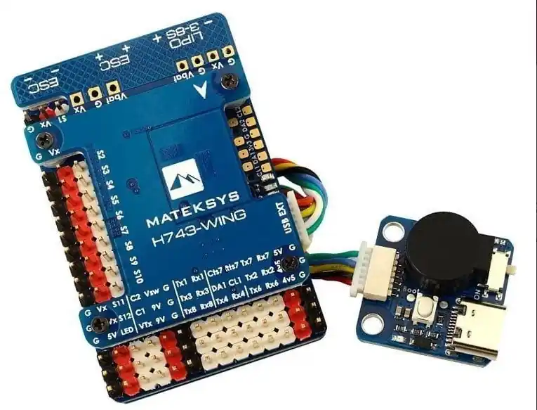
MATEK H743-WING
kontroler lotu do samolotu
Procesor : STM32H743VIT6, 480MHz , 1MB RAM, 2MB Flash
Gyro : MPU6000 (SPI1) & ICM20602 (SPI4)
Baro : Infineon DPS310 (I2C2)
Betaflight OSD
Blackbox: 32MB
BEC: 5V / 2A , 9V(12) / 2A , 5V (6V , 7.2V) / 8A dla serw
7x UART
Wymaga znajomości programowania i obsługi kontrolerów lotu.
Polecane oprogramowanie: ArduPilot MATEKH743 lub INAV wkrótce
FC Specifications
- MCU: STM32H743VIT6, 480MHz , 1MB RAM, 2MB Flash
- IMU: MPU6000 (SPI1) & ICM20602 (SPI4)
- Baro: Infineon DPS310 (I2C2)
- OSD: AT7456E (SPI2)
- Blackbox: MicroSD card slot (SDIO)
- 7x Uarts (1,2,3,4,6,7,8) with built-in inversion.
- 13x PWM outputs(including “LED” pad)
- 2x I2C
- 1x CAN
- 6x ADC (VBAT, Current, RSSI, Analog AirSpeed, VB2, CU2)
- 3x LEDs for FC STATUS (Blue, Red) and 3.3V indicator(Red)
- 1x SPI3 breakout
- USB/Beep Extender with Type-C(USB2.0)
- Dual Camera Inputs switch
- 5V/9V(12V) for Camera/VTX power switch
- High-precision Current Sense
- ADC VB2 voltage divider: 1K:10K
- ADC AirSpeed voltage divider: 10K:10K
- INAV TR/SA VTX control: Yes
- Beeper : Yes
- RSSI: Yes
- Analog Airspeed sensor: Yes
- Digital Airspeed sensor: Yes
- Static power 160mA@5V
FC Firmware
- ArduPilot(ChiBiOS): MATEKH743
- INAV: MATEKH743 (To be supported soon)
- BetaFlight: MATEKH743
PDB
- Input voltage range: 9~36V (3~8S LiPo) w/TVS protection
- 2x ESC power pads
- Battery Voltage Sensor: 1:10 (Scale 1100 in INAV, BATT_VOLT_MULT 11.0 in ArduPilot)
- Current Senor: 132A, 3.3V ADC (Scale 250 in INAV, 40 A/V in ArduPilot)
- Sense resistor: 60A continuous, 132A burst.
BEC 5V output
- Designed for Flight controller, Receiver, OSD, Camera, Buzzer, 2812 LED_Strip, Buzzer, GPS module, AirSpeed
- Continuous current: 2 Amps, Max.3A
BEC 9V /12V output
- Designed for Video Transmitter, Camera, Gimbal ect.
- Continuous current: 2 Amps, Max.3A
- 12V option with Jumper pad
BEC Vx output
- Designed for Servos
- Voltage adjustable, 5V Default, 6V or 7.2V via jumper
- Continuous current: 8 Amps, Max.10A
BEC 3.3V output
- Linear Regulator
- Continuous current: 200mA
Physical
- Mounting: 30.5 x 30.5mm, Φ4mm with Grommets Φ3mm
- Dimensions: 54 x 36 x 13 mm
- Weight: 30g with USB extender
Including
- 1x H743-WING
- 1x USB/Beep Extender
- 1x 20cm SH-4P to GH-4P cable for CAN port
- 1x 20cm SH-6P to SH-6P cable for USB extender.
- Dupont 2.54 pins (Board is shipped unsoldered)
ArduPilot Mapping
ArduPilot Relay
- Camera-1 and Vsw On by default
- Make sure 2 cameras are set with identical video format, both PAL or both NTSC.
# GPIOs
- PD10 PINIO1 OUTPUT GPIO(81) //Vsw pad power switch
- PD11 PINIO2 OUTPUT GPIO(82) //Camera switch
# RCx_OPTION: RC input option
- 28 Relay On/Off
- 34 Relay2 On/Off
- 35 Relay3 On/Off
- 36 Relay4 On/Off
e.g.
- RELAY_PIN 81 //Vsw GPIO
- RC7_OPTION 28 //Relay On/Off, Use CH7 of Transmitter to switch Vsw
- RELAY_PIN2 82 //Camera switch GPIO
- RC8_OPTION 34 //Relay2 On/Off, Use CH8 of Transmitter to switch camera
or
- RELAY_PIN3 81 //Vsw GPIO
- RC9_OPTION 35 //Relay3 On/Off, Use CH9 of Transmitter to switch Vsw
- RELAY_PIN4 82 //Camera switch GPIO
- RC10_OPTION 36 //Relay4 On/Off, Use CH10 of Transmitter to switch camera
The configured feature will be triggered when the auxiliary switch’s pwm value becomes higher than 1800. It will be deactivated when the value falls below 1200.
Check the pwm value sent from the transmitter when the switch is high and low using the Mission Planner’s Initial Setup >> Mandatory Hardware >> Radio Calibration screen. If it does not climb higher than 1800 or lower than 1200, it is best to adjust the servo end points in the transmitter.
Tips
ArduPilot Firmware ” MATEKH743″
- Only beta/latest ArduPilot firmwares after Jun.25 support the onboard barometer currently.
- https://firmware.ardupilot.org/Plane/latest/MatekH743/
- https://firmware.ardupilot.org/Copter/latest/MatekH743/
- H743-WING has betaflight firmware preloaded for QC
- If you flash ArduPilot firmware via BetaFlight configurator. there is a known issue that flash process will freeze at 50% if “full chip erase” is selected. Disable full chip erase when flashing, then reset to default in Mission Planner after flashing.
- It is highly recommended to use STM32CubeProgrammer to erase MCU and upload firmware http://www.mateksys.com/?p=6905